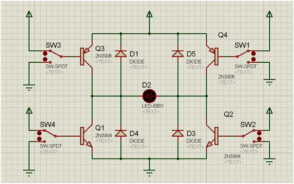
Figure 1: H-bridge circuit diagram
Above Figure 1 is the diagram for the H-bridge. Switches that are used to control the logic level are SW1, SW2, SW3, and SW4. D1, D3, D4, and D5 diodes are used to protect the reverse flow. The circuit in Figure 1 shows that the supplies to the load a well as the control are tied together. However, this can be separated if the load requires additional current and voltage. Both Figure 1 and Figure 2 shows the supply voltage in 2 different direction.
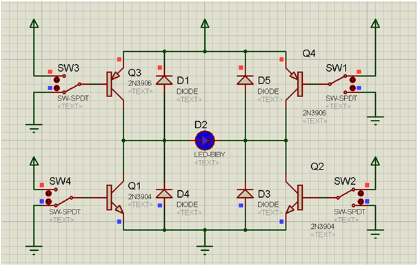
Figure 2: Q3 low Q2 high
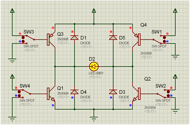
Figure 3: Q4 low Q1 high
The circuits below will show the H-Bridge implementation using 2 switches instead of 4.
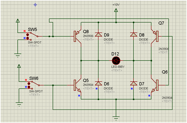
Figure 4: Controlling with 2 input
Figure 5 shows when SW5 and SW6 are low.

Figure 5: SW5, SW6 low
In order for the H-Bridge to work, either one of the switch SW5 or SW6 has to be high while the other switch has to be low.
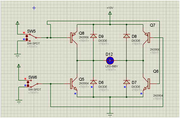
Figure 6: SW5 high, SW6 low
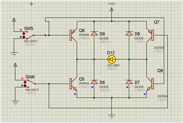
Figure 7: SW5 low, SW6 high
Conclusion
The discussion above shows the implementation of the H-bridge to control direction. This can be used to control motor in both direction by controlling the switches. The proteus simulation above is used to test, debug as well as simulate the concept of the circuit to make sure that the circuit is workable.
Your blog are impressive to each other.I read your blog. useful content .its very good, Help ful for all. Thank you for sharing this.
ReplyDeleteBest Embedded System Training in Chennai
ReplyDelete