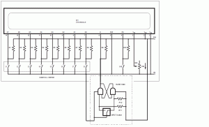
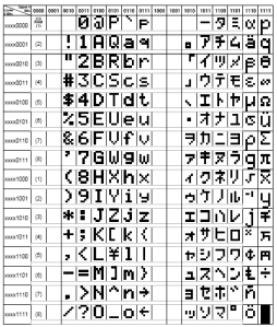
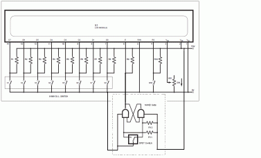
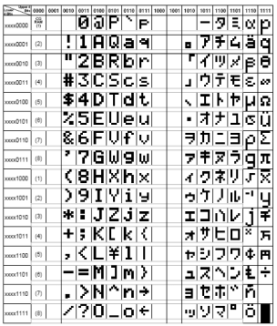
 From the diagram above, we can see that extra circuit is required before any input is available to the Enable(E) pin of the LCD. This circuit is actually a debounce circuit built from two NAND gate logic. If this debounce circuit is not addded, then, what will happens is that, whenever the input changes from logic 1 to logic 0 at the Enable pin while PS pin is logic 1, the LCD will display the predefined character from D7D6D5…D2D1D0. By allowing debouncing on E pin to occur, the LCD will display multiple of the first character until the switch is stable. Below is the table that defines the characters that the LCD can display with the equivalent binary codes.
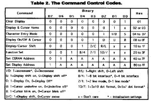
 In order to command the LCD to do a specific task, command code is needed. Thus, the following table will show the tasks with the equivalent hex code:
To begin,
- Set E, RW, RS to 0.
- Set D7D6D5…D2D1D0 to 0001111.
- Set E to 1.
- Set D7D6D5…D2D1D0 to 0000000.
- Set RS to 1.
- Set the appropriate letter to be displayed on D7D6D5…D2D1D0.
- Set E to 1 to display. Then, Set E back to 0.
- Continue the above steps until message is displayed.
